
There are plenty of babyphones available for purchase. What they have in common is that you can’t integrate them into an existing smart home environment since they’re often quite proprietary, build on top of DECT or go through some cloud and one doesn’t want microphone data to go through a cloud of a stranger. Also in my opinion, the price is too high for what you get. So let’s DIY a babyphone that will communicate with my existing smart home hub!
In the next paragraphs I’ll describe some challenges I was faced with while trying to DIY a babyphone.
Hardware needed
My first intention was to use a raspberry pi and a microphone. But since that’s a bit oversized, I decided to once more take one of those cheap ESP 8266 microcontrollers and connect it to a microphone module. I decided to buy a MAX9814 module simply because it was quite low in price (5,99€). After some soldering I put everything together and started to think about the possibilities.
The goal
The idea behind a babyphone is to get alarmed when a baby awakes and needs some care. As I’ve noticed during the first weeks, the newborn cries when he wakes up. Crying is quite loud so why not just have a device that will listen to noise of the given level and send some notifications if the noise continues for a given amount of time.
With such a notification many different alarming events can be triggered: You could automatically turn on the light in some rooms, start playing music, give some light flashes in the living room, put a notification on the television… Sky's the limit. But first things first.
The software
In the first days and weeks of my ESP DIY times, I did everything by myself, just so that I could learn the code and the ideas behind. This time I’ll try to use ESPHome, a system that covers the basic steps like, WIFI-Setup, communication with the smart home hub and OTA updates. With this being done out of the box, it’s time to listen to the noise of babies:
The MAX9814 will give us an analogue output of about 2V with an offset of 1.25V according to the datasheet. The output is connected to the A0 (analogue input) pin of the ESP8266 microcontroller and when we fire it up and listen to that pin, changes in Voltage should occur based on the loudness of the surrounding noise.
The basic setup of a esphome node
Let’s start with the basic configuration for the microcontroller. The following command will create a template configuration for the node and ask for WiFi ssid, passphrase and some other secure tokens for OTA updates.
esphome babyphone.yaml wizard
Once finished, with the microcontroller connected to the USB port of the computer, you can deploy ESPhome by calling the command:
esphome babyphone.yaml runWhen successful, you’ll see some output containing connection details, IP address etc. The device is ready and can be used for further development. Since OTA is running now, you don’t need the direct USB connection anymore.
Get the microphone data
With the node up and running it is about time to get first data from the attached microphone. As mentioned above, it will put some voltage on the A0 pin based on the surrounding noise level. Let’s see if we can simply output the voltage. Adding an adc sensor
sensor:
  - platform: adc
    pin: A0
    name: "babyphone microphone level"
    update_interval: 1
and deploying everything will give us some log output with the new microphone level in Volt. Making some artificial noise we can easily check the configuration: if you produce some noise and the voltage level changes, things are running as expected. And thanks to ESPhome data points will already be transmitted for further processing. So are we done yet?
Unfortunately we’re still far from being done! With an update interval of only one second we only get a sampling rate of 1 Hz for the sound analysed through our basic ADC. According to the Nyquist–Shannon sampling theorem we would only get a signal of below 0.5 Hz which is far below, what we can hear (20-20000Hz technically, 20-14000Hz for middle aged folks - with a highest sensitivity from nearly 500 to 5000Hz according to the Equal loudness curves). I’m not an audio engineer, but I’d assume that we will have to increase the sampling rate significantly to really get into the noise spectrum of a crying baby.
Spectrum of noise
To analyze the spectrum I recorded a short sample of the child crying. It wasn't that hard to get the sample. Let’s analyse the sound using a Spectogram:
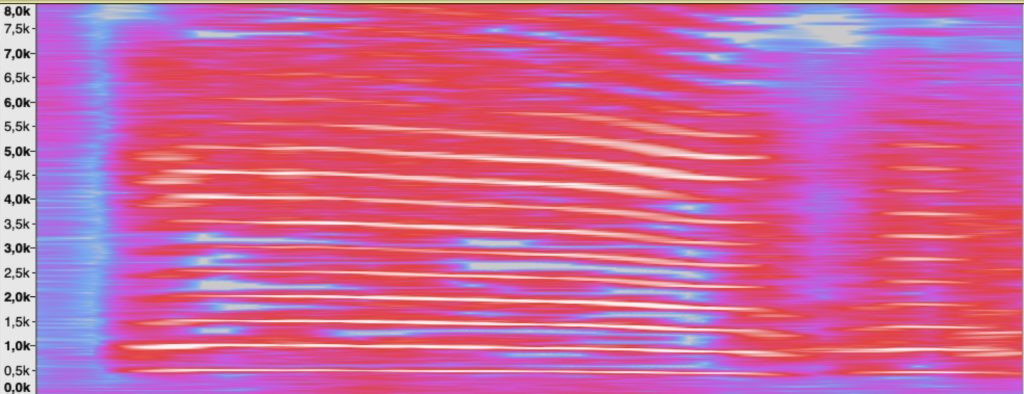
Based on the recording, baby screaming consists of multiple peeks at several frequencies. To talk through the picture, we have continuous peeks at 500Hz, 1kHz, 1.5kHz and so on and some higher peaks of 3.5kHz, 4kHz going up in 500Hz steps as it seems. There is a cutoff over 8 kHz as I have only recorded a limited spektrum. So what does it mean:
Well, there is not much noise below 500Hz in this case. But with a sampling rate of 1s we’re not even close to capture frequencies at 500Hz: Our microcontroller simply won't hear anything at all! How can we mitigate this?
Tick tock, tick tock
According to Nyquist-Shannon-Sampling-Theorem our sampling rate has to be at least double the frequency we want to capture. In our case somewhere over 12kHz to capture sound below the 5.5kHz threshold (check the spektrogram above). That's not a big deal with a ESP8266 as it is clocked with around 80MHz (and more). But as it's a single core device, we share the computational resources with ESPhome: This includes WiFi, protocols, logging and everything else that makes ESPhome so handsome. With a custom sensor component written in C++, we can speedup things and go up to nearly 60 loops or samples per second according to ESPhome.io documentation. That would give us a sound spectrum of only 24Hz at best. Quite disappointing as it looks like we won’t come far enough with this approach.
There is never a problem but always a challenge
To recap, what looked as an easy task, acutally isn't that easy. Due to some technical limitations and based on what we know so far, we can’t get what we want with one simple 8266 microcontroller running ESPhome and a basic microphone. Easiness comes at a price and ESPhome eats up most computational resources in such a way that there is not enough left to have a high enough sampling rate with our DIY ADC - we're gearing up now.
There are several well known software engineering strategies to handle this:
- we could get rid of ESPhome and write highly optimized and specialized software from scrantch that will utilize the available resources perfectly.
-
we could throw more hardware on this particular challenge by:
a) using a second dedicated 8266 to only handle the microphone with a much higher sampling rate and return only relevant information and events to the first ESPhome based 8266.
b) putting a dedicated ADC in between the microphone and ESPhome 8266 that has a higher sampling rate and outputs digital audio that can be further processed with less resources.
Which way to go? I personally prefer option 2 as this sounds like more fun, to be honest. As of the suboptions, interestingly both will cost the same few Euros, but since I own many microcontrollers, no further investment is needed and so option 2a it is.
But for now it's about time to have a break and take care of the crying baby.